Completed Collaborative Projects at CSVRC
Neurosurgery
Hemodynamics & Quantitative Imaging
Medical Physics
Models of ischemic stroke and aneurysm
Medical Physics
Hemodynamics & Quantitative Imaging
Medical Physics
Improving diagnostic imaging in order to facilitate accurate diagnosis, optimal patient safety and treatment outcomes.
Hemodynamics & Quantitative Imaging
Hemodynamics & Quantitative Imaging
Hemodynamics & Quantitative Imaging
Investigating blood flow dynamics & vessel wall integrity
Neurosurgery
We researched and developed a wide variety of in vivo, in vitro, and bench top models to address the diversity present in both academic and commercial environments and are able to provide experienced assistance in every aspect from study and protocol development to analyzing final results.
Some of the in vivo models we research and develop include:
- An array of aneurysm morphologies in various species
- Liquid embolic evaluation
- Custom bench top and surgical models
- Associated pathology and histologic staining through partners
Dr Adnan H Siddiqui, Professor in the Neurosurgery Department, Dr. Elad Levy, Professor and Chairman of the Neurosurgery Department and Dr Kenneth Snyder head the Center’s research in Neurosurgery. Together with the researchers and neurosurgery fellows they work closely with the Department of Neurosurgery in the University at Buffalo and Kaleida Health to improve current devices and advance knowledge of the development of vascular disease. This is accomplished by providing an area where clinicians can participate with researchers and industry to develop our own technology and research models investigating the origin of disease states, as well as contributing to the work of others.

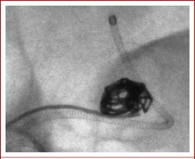
A DSA image shows a clot was placed & retrieved with a stent retriever from the left MCA.
Medical Physics

Dose Measurements & Quality Assurance
X-ray based medical imaging is a complex process which involves x-ray production, interaction of the radiation with mater, radiation detection, image formation and post processing. To reduce effects of ionization on live tissue while maintaining high image quality, medical physicists dedicate a lot of effort to optimize such x-ray systems. A part of the research in our group is focused on the development of standard radiographic phantoms and analysis methods. We developed standard phantoms equivalent to human anatomy which were used successfully to improve imaging and detectors.
Left/above photo: Radiographic evaluation of various contrast metrics using different views through an head equivalent views

Scatter Reduction
An age-old problem in radiographic imaging is contrast and signal to noise ratio (SNR) reduction due to Compton scattering, the most probable interaction of medical x-rays with soft tissue. We pioneered a scanning beam scatter reduction method for rapid sequence imaging and applied ROI attenuation as well; however, the most common method for scatter reduction, the convenient-to-install grid, creates grid-line structured artifacts that appear as structured noise even if it oscillates during an exposure. These structures become more significant for higher resolution detectors and so we have been developing methods to divide out the grid noise patterns.
Left/above photo: Example of grid artifacts in a x-ray detector (left- 7a) and correction (right-7b).

Region of Interest Imaging
As image guided interventional procedures continue to replace invasive surgical procedures and longer patient x-ray exposure times are required, there is an urgent need to reduce patient dose without jeopardizing outcomes. We have pioneered ROI techniques to achieve this goal by preserving the best image within the ROI while reducing dose peripheral to the ROI. With recent digital imaging developments we have been able to further improve real-time ROI imaging using differential temporal filtering to reduce noise especially outside the ROI and we have even combined ROI dose reduction and high resolution MAF imaging for biplane image guidance.

Micro-Computed Tomography
Micro–Computed Tomography is based on Cone Beam Computed Tomography which is a imaging modality used in hospital CT scans or angiography units, but on a small scale with increased resolution. Theses systems are used for non destructive 3D microscopy. We build our own system where we employed our own x-ray detectors. The system has resolution of 8 microns and uses a control software and reconstruction developed by our staff. The system has been used for endovascular devices integrity study, bone structure, tumor imaging, etc.
Left/above photo: Micro-CT sections of explanted aneurysms treated with 2 types of Asymmetric Stent taken at 3 positions, as indicated in the schematic. Brighter dots are the nitinolstruts of the stents, white arrows indicate the soft tissue, and dotted arrows indicate the holder.

Bone Structure Evaluation
The bone is a complex tissue which regulates its mass and architecture to satisfy the structural and metabolic necessities. The bone structure the body framework and it serves as a mineral reservoir. Our Micro-CT system has been extensively used to scan bone structures. Our home built detectors provide extremely high resolution and sensitivity unmatched by current flat panel technologies. We provided vital data to research groups working in dentistry, regenerative materials, implants and ageing. In addition to raw data we developed software which can calculate various morphological parameters such as: bone surface, trabecular volume, trabecular thickness, trabecular separation number and fractal dimension.

Cone Beam CT
Cone beam computed tomography (CBCT) is a medical imaging technique similar to computed tomography. The X-rays are divergent, forming a cone incident on a detector. The entire system is placed on a C-arm which can rotate around the patient. CBCT has become routine procedure in treatment planning and diagnosis cardiovascular disease. Our group uses such imaging modality on a regular basis. We have focused mostly in implementation of region of interest detectors which could be used to give high resolution volumes in a particular area. We also work on new reconstruction algorithms and acquisition to optimize the image quality while decreasing the dose delivered to the patient.

Angiography
Angiography is a medical imaging technique used to visualize the blood vessels lumen. This is done by injecting a radio-opaque contrast agent, such as Iodine, into the blood vessel via a catheter and imaging using X-ray imaging. This is a diagnosis technique which uses larger x-ray exposures for a very short period of time. We have worked with industry engineers to improve the quality of the images by improving hardware, imaging devices and software. In addition, novel analysis methods were developed to estimate physiological blood flow based only on angiography.
Left/above photo: Digital subtraction angiography (DSA) images acquired with the standard x-ray image intensifier demonstrate no residual filling of the aneurysm.
X-ray Fluoroscopy
X-ray fluoroscopy is an medical imaging modality used to obtain real-time moving images. The image acquisition rate is high to allow real time visualization of internal organ motion or two guide an intervention where an interventionalist observes the motion and the position of a device in a patient. Due to extensive use the x-ray exposure is low to avoid dose and could lead to noisy images. Our group has been involved in novel approaches to improve the image quality while decreasing the dose. This involved development of new hardware, imagers and software, some of which are implemented on clinical units.
Left/above video: high definition fluoroscopy of a pipeline device deployment in a simulated model.

High Resolution Imaging & Detectors
During endovascular interventions it is necessary to have the best possible real-time image guidance especially at critical stages of the intervention but only over the region of interest of the pathology being treated. For this reason we have been developing high resolution dynamic detectors that far exceed the capabilities of current imagers. Prototypes of these Micro-Angiographic Fluoroscopy (MAF) detector systems have received laudatory acceptance by clinicians. It is expected that soon these new capabilities will become the new standard of care first in neurovascular interventions and later in pediatrics, cardiology and other applications.
Hemodynamics & Quantitative Imaging

Devices and Phantoms
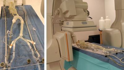
Vascular phantoms are a very important tool for benchtop testing of new devices and procedure. 3D printing offers a great opportunity to create testing settings very similar to the clinical situations. Using our 3D printing facility we created a plethora of patient specific arterial geometries based on CT, MRI or CBCT from patient data. Patient data acquired using various imaging modalities is loaded into a 3D station for 3D rendering and processing. We manually select the vessel of interest and perform a dynamic vessel growing and export the geometry as 3D meshes in a Stereo-Lithographic (STL) File, which will be uploaded in a mesh manipulation software. Using this software we manipulate the model to merge outlets and support in order to make a friendly benchtop model. We created full Circle of Willis models, aneurysm models, cardiac models and aortic arch models. These models can be interconnected and attached to a pump to simulate physiological flow. We use these models to simulate ischemic stroke and treatment, aneurysm treatment and diagnosis.

Asymmetric Flow Diverter
One approach to treat intracranial aneurysms is to use stent-like flow diverters to create thrombogenesis conditions in the aneurysm with minimal sack manipulation. Ninety percent of IA’s occur at a bifurcation, potentially in the vicinity of smaller branches. Therefore, the devices need to be flexible for easy deliverability and porous enough to avoid adjacent arterial branches occlusion, which could cause additional strokes. One of the simple Uniform Flow Diverters (UFD) being used in restricted human cases, while effective in some sidewall IA’s, is inappropriate for usage with bifurcation aneurysms. We have been heavily involved in a research projects to investigate, develop and optimize the design of a new Asymmetric Flow Diverter (AFD), for treatment of bifurcation IA’s without the short-comings associated with current uniform flow diverting stents. The new device would consist of a low-porosity region which will cover only the aneurysm neck, to effectively divert the flow. The rest of the device will be high-porosity to reduce the chance of blockage of adjacent arteries. We treated in-vitro and in-vivo bifurcation IA’s models using the new AFDs, and studied the flow changes in the aneurysm dome and in the adjacent branches.
Left/above photo: A−C, Self-expanding Asymmetric Flow Diverter devices. Upper: Photographs of the 3 types of these stents. Lower: Angiograms showing deployment of types A and B. Type A contains a sleeve (PTFE patch) approximately 4–5 mm wide covering the central part of the stent; types B and C have a patch covering only a given stent region. Types A and B have a closed-cell structure, whereas type C has an open-cell structure. In the photographs, black arrows indicate the platinum markers used to guide the stents during the procedure and dotted arrows indicate the marker position not visible in photographs.